EdgeRouter - OSPF Routing
How to Configure OSPF Routing
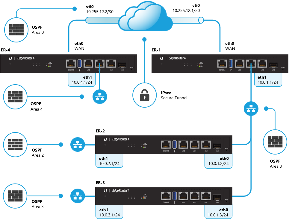
OSPF will be used to provide reachability between the 10.0.4.0/24 and the 10.0.0.0/22 networks over the Site-to-Site VPN.
In the example diagram above, all of the EdgeRouters are ABRs (Area Border Routers) and contain an active interface in OSPF area 0 and another area. There is a Site-to-Site VPN configured between ER-4 and ER-1, over which the OSPF adjacency is established and the routing information for the 10.0.4.0/24 and 10.0.0.0/22 networks is exchanged. There is more information about VPNs in the Route-Based Site-to-Site IPsec VPN article.
Follow the steps below to enable the OSPF process on the relevant interfaces of all routers:
CLI: Access the Command Line Interface on ER-4.You can do this using the CLI button in the GUI or by using a program such as PuTTY.
1. Enter configuration mode.
configure
2. Define the OSPF network type for the vti0 interface.
Copy
set interfaces vti vti0 ip ospf network point-to-point
3.![]() Define a custom OSPF router ID.
Define a custom OSPF router ID.
Copy
set protocols ospf parameters router-id 0.0.0.4
4. Enable the OSPF routing process on the relevant interfaces and define the OSPF area number.
Copy
set protocols ospf area 0 network 10.255.12.0/30
set protocols ospf area 4 network 10.0.4.0/24
5.![]() Set all interfaces to passive, with the exception of interfaces that should form adjacencies with other OSPF routers.
Set all interfaces to passive, with the exception of interfaces that should form adjacencies with other OSPF routers.
Copy
set protocols ospf passive-interface default
set protocols ospf passive-interface-exclude vti0
set protocols ospf passive-interface-exclude eth1
NOTE: Interfaces which are set to passive are unable to form OSPF neighborship adjacancies.
6. Commit the changes and save the configuration.
commit ; save
CLI: Access the Command Line Interface on ER-1.
1. Enter configuration mode.
configure
2. Define the OSPF network type for the vti0 interface.
Copy
set interfaces vti vti0 ip ospf network point-to-point
3. Define the OSPF network type for the eth1 interface and lower the priority to 1.
Copy
set interfaces ethernet eth1 ip ospf priority 1
set interfaces ethernet eth1 ip ospf network broadcast
NOTE: Lowering the OSPF priority ensures that ER-1 becomes the DR (Designated Router) on the 10.0.1.0/24 LAN segment.
4.![]() Define a custom OSPF router ID.
Define a custom OSPF router ID.
Copy
set protocols ospf parameters router-id 0.0.0.1
5. Enable the OSPF routing process on the relevant interfaces and define the OSPF area number.
Copy
set protocols ospf area 0 network 10.255.12.0/30
set protocols ospf area 0 network 10.0.1.0/24
6. ![]() Set all interfaces to passive, with the exception of interfaces that should form adjacencies with other OSPF routers.
Set all interfaces to passive, with the exception of interfaces that should form adjacencies with other OSPF routers.
Copy
set protocols ospf passive-interface default
set protocols ospf passive-interface-exclude vti0
set protocols ospf passive-interface-exclude eth1
5. Commit the changes and save the configuration.
commit ; save
CLI: Access the Command Line Interface on ER-2.
1. Enter configuration mode.
configure
2. Define the OSPF network type for the eth0 interface.
Copy
set interfaces ethernet eth0 ip ospf network broadcast
3.![]() Define a custom OSPF router ID.
Define a custom OSPF router ID.
Copy
set protocols ospf parameters router-id 0.0.0.2
4. Enable the OSPF routing process on the relevant interfaces and define the OSPF area number.
Copy
set protocols ospf area 0 network 10.0.1.0/24
set protocols ospf area 2 network 10.0.2.0/24
4. ![]() Set all interfaces to passive, with the exception of interfaces that should form adjacencies with other OSPF routers.
Set all interfaces to passive, with the exception of interfaces that should form adjacencies with other OSPF routers.
Copy
set protocols ospf passive-interface default
set protocols ospf passive-interface-exclude eth0
5. Commit the changes and save the configuration.
commit ; save
CLI: Access the Command Line Interface on ER-3.
1. Enter configuration mode.
configure
2. Define the OSPF network type for the eth0 interface.
Copy
set interfaces ethernet eth0 ip ospf network broadcast
3.![]() Define a custom OSPF router ID.
Define a custom OSPF router ID.
Copy
set protocols ospf parameters router-id 0.0.0.3
4. Enable the OSPF routing process on the relevant interfaces and define the OSPF area number.
Copy
set protocols ospf area 0 network 10.0.1.0/24
set protocols ospf area 3 network 10.0.3.0/24
4. ![]() Set all interfaces to passive, with the exception of interfaces that should form adjacencies with other OSPF routers.
Set all interfaces to passive, with the exception of interfaces that should form adjacencies with other OSPF routers.
Copy
set protocols ospf passive-interface default
set protocols ospf passive-interface-exclude eth0
5. Commit the changes and save the configuration.
commit ; save
After finalizing the OSPF configuration, the OSPF neighbor table and interfaces on ER-1 looks like this:
show ip ospf neighbor
Total number of full neighbors: 3

OSPF process 0 VRF(default):
Neighbor ID     Pri   State            Dead Time   Address         Interface           Instance ID
0.0.0.2           1   Full/Backup      00:00:38    10.0.1.2        eth1                    0
0.0.0.3           1   Full/DROther     00:00:33    10.0.1.3        eth1                    0
0.0.0.4           1   Full/ -          00:00:31    10.255.12.2     vti0                    0

show ip ospf interface
vti0 is up, line protocol is up
 Internet Address 10.255.12.1/30, Area 0.0.0.0, MTU 1436
 Process ID 0, VRF (default), Router ID 0.0.0.1, Network Type POINTTOPOINT, Cost: 10
 Transmit Delay is 1 sec, State Point-To-Point, TE Metric 10
 Timer intervals configured, Hello 10, Dead 40, Wait 40, Retransmit 5
 Neighbor Count is 1, Adjacent neighbor count is 1
 <output shortened>

eth1 is up, line protocol is up
 Internet Address 10.0.1.1/24, Area 0.0.0.0, MTU 1500
 Process ID 0, VRF (default), Router ID 0.0.0.1, Network Type BROADCAST, Cost: 10
 Transmit Delay is 1 sec, State DR, Priority 1, TE Metric 10
 Designated Router (ID) 0.0.0.1, Interface Address 10.0.1.1
 Backup Designated Router (ID) 0.0.0.2, Interface Address 10.0.1.2
 Timer intervals configured, Hello 10, Dead 40, Wait 40, Retransmit 5
 Neighbor Count is 2, Adjacent neighbor count is 2
 <output shortened>
The OSPF routing table on ER-3 look like this:
show ip route ospf

IP Route Table for VRF "default"
O IA *> 10.0.2.0/24 [110/11] via 10.0.1.2, eth0, 00:01:44
O *> 10.255.12.0/30 [110/20] via 10.0.1.1, eth0, 00:01:44
O IA *> 10.0.4.0/24 [110/21] via 10.0.1.1, eth0, 00:01:44